nstrument engineers are responsible for providing safe
and appropriate instrumentation. To declare a system
safe, simply because a single component is approved,
is dangerous in more ways than one.
Two important factors should be considered whenever a job involves electrical equipment in a hazardous location:
 |
Safety. Is the equipment specified truly safe to use in the proposed environment? If the answer is yes, then on what premise is that answer based? |
| |
|
 |
Liability. If you have determined that the equipment specified is safe, are you prepared to defend that determination in a court room? |
No one wants to be responsible for injuring others, especially when easily obtainable safeguards exist. In the event of an unfortunate incident, the consequences can be punitive if the injured party can prove that the designer did not take all reasonable and prudent measures to protect against predicable hazards.
In the event of an accident involving an explosion in a hazardous environment, the attorneys for the injured party will attempt to prove negligence on the designer's part. To do this, they usually will retain some individual or organization recognized as an expert in the field. The designer might be asked what measures were taken to ensure that the equipment was safe. Then, their expert would attempt to point out items missed or not listed under direct examination.
In the United States, Factory Mutual Research Corp. (FMRC) is recognized as one of the experts in the field of industrial safety. For certain installations, many companies, local governments and regulatory agencies require that all electrical equipment must be approved by FM and Underwriters Laboratories (UL). In general, these rules and regulations spell out the location's category by class, division and group. (See Sidebar)
When an installation requires that electrical-measuring instruments be placed in locations that are considered hazardous, it is incumbent upon the engineer to see that the installation is safe. The user generally will specify the degree of safety required. For example, a petrochemical company could specify that supplied equipment must be explosion proof for Class I, Division 1, Group B. The user is being very specific as to the level of security expected, referring to Article 500 of the National Electrical Code. Factory Mutual subscribes to this code and references it in their approval guide.
When an installation requires that electrical-measuring instruments be placed in locations that are considered hazardous, it is incumbent upon the engineer to see that the installation is safe. The user generally will specify the degree of |
|
safety required. For example, a petrochemical company could specify that supplied equipment must be explosion proof for Class I, Division 1, Group B. The user is being very specific as to the level of security expected, referring to Article 500 of the National Electrical Code. Factory Mutual subscribes to this code and references it in their approval guide.
In general, the classification defines the extent of the hazard, taking into account the energy required to ignite certain gas mixtures and the potential forces released as a result. When an assembly is called explosion proof, the sensor assembly manufacturer is certifying to the user that specific steps have been taken to ensure the safety of all Plant personnel.
But, no chain is stronger than its weakest link; likewise, no system is explosion proof if it contains non-explosion proof components. Systems are rendered explosion proof by two means:
• Design the system so that it cannot release sufficient electrical or thermal energy to ignite the specified gas mixture. Such systems are classified as intrinsically safe.
• Design the system such that it is capable of containing an internal explosion of a specified flammable vapor air mixture and may contain sufficiently long thread paths such that any escaping gases will be cooled below the ignition temperature of the surrounding atmosphere.
CASE IN POINT:
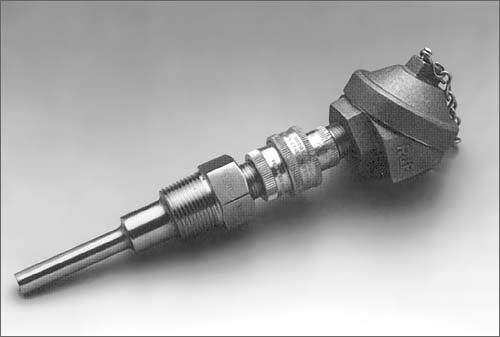
Installing a temperature sensor in a hazardous location requires more than an approved explosion proof connection head. To meet the safety requirements of FM, you must consider the complete system: including the sensor, the thermowell (if required and used) and the connection head.
Each component in the system must meet the code. For example, many thermowells are supplied with 1/2-14 NPSM threads for the sensor connection. FM dictates that to meet the requirements for explosion proof, a tapered thread is required. Most sensors are supplied with a 1/2-14 NPT thread; however, FM also specifies a meinimum thread engagement between the sensor and the connection head. The thread engagement requirement makes it necessary to overcut the thermowell thread beyond the ASME definition of 1/2-14 NPT.
Those manufacturers wishing to offer explosion proof assemblies must meet FM's requirements. Once a design is constructed with the proper thread size and engagement between the head cover, head body, wire conduit and seal, sensor, lag fittings and thermowell, the manufacturer submits the design to FM for testing to ensure that the specified gas mixtures are properly contained. Once approved by FM, the manufacturer is not permitted to alter any of the approved configurations without FM approval. If changes are
|