

RTDs / Probe RTDs : Series 21 1/4” dia.
Series 21: 1/4” dia. Industrial Platinum RTD Probes
PNs 21A, 21B, 21C, 21D, 21H
Ordering Specifications
STRAIGHT PROBE ASSEMBLIES
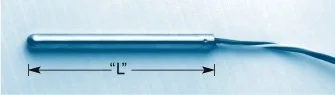
TYPE 21A
Features: 1/4" dia. 316 SS sheath; operating range –320°F to 900°F, Teflon® insulated lead wires; single or dual elements, RdF Reference or IEC/DIN R vs. T characteristics, and 2, 3 or 4 wire element configurations.
RIGID PROBE ASSEMBLIES WITH
HERMETICALLY SEALED CONNECTOR
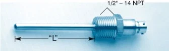
TYPE 21C
Features: 1/4" dia. 316 SS sheath with hermetically sealed 4-pin connector; operating range –320°F to 900°F single or dual elements; RdF Reference or IEC/DIN R vs. T characteristics, and 2, 3 or 4 wire configurations.
*P/N 53105 (Mating Connector) must be ordered separately.
HERMETICALLY SEALED
PROBE ASSEMBLIES
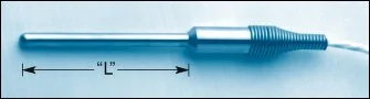
TYPE 21H
Features: 1/4" dia. SS sheath; operating range –320°F to 900°F; Teflon® insulated 3-conductor cable; RdF Reference or IEC/DIN R vs. T characteristics. Integral hermetic seal. Single element only.
Ordering Specifications
| 21A/C/H | ||||||||||||||||||||||||
| RTD RESISTANCE SPECIFICATIONS (Ohms @ 0°C) 10 100 ± 0.1 (α = 0.003924 Ω/Ω/°C) RdF Ref. Std. 11 100 ± 0.1 (α = 0.00385 Ω/Ω/°C) IEC/DIN Std. T01 100 + 0.12 (α = 0.00385 Ω/Ω/°C) thin film 20 200 ± 0.2 (α = 0.003924 Ω/Ω/°C) 21 200 ± 0.2 (α = 0.00385 Ω/Ω/°C) T05 500 ± 0.6 (α = 0.00385 Ω/Ω/°C) thin film T10 1000 ± 1.2 (α = 0.00385 Ω/Ω/°C) thin film 102* 100 ± 0.1 Dual Element (α = 0.003924 Ω/Ω/°C) 112* 100 ± 0.1 Dual Element (α = 0.00385 Ω/Ω/°C) T012* 100 ± 0.12 Dual Element (α = 0.00385 Ω/Ω/°C) thin film *Not Available on 21H |
||||||||||||||||||||||||
| SERVICE PARAMETER – Sinusoidal Vibration 20Hz to 2kHz S Standard construction (25 g wire-wound, 80 g thin film) H Heavy-duty construction (up to 50 g) (1 wire element only) |
||||||||||||||||||||||||
| PROBE LENGTH (Specify “L” in inches) Std. Const: 3" minimum, Heavy Duly: 3" minimum for 21H, 4" minimum for 21A & 21C (see photos) |
||||||||||||||||||||||||
|
||||||||||||||||||||||||
| ARMOR LENGTH (21A only) Specify “X” in inches (ie. A0= no armor, A60 = 60 inches) (Single element only) |
||||||||||||||||||||||||
| LEAD LENGTH - Specify in inches (Not applicable to 21C) |
||||||||||||||||||||||||
|
|
|
|
|
|
|
Typical write-up for 21A | |||||||||||||||||||||||||||||||||||||||||||||||||||||||||||||||||||||||||||||||||||||||||||||||||||
|
|
|
|
|
|
|
Typical write-up for 21C | |||||||||||||||||||||||||||||||||||||||||||||||||||||||||||||||||||||||||||||||||||||||||||||||||||
RIGID PROBE ASSEMBLIES
WITH HEX FITTING
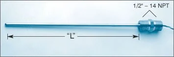
TYPE 21B
Features: 1/4" dia. 316 SS sheath; operating range –320°F to 900°F, Teflon® insulated lead wires; single or dual elements, RdF Reference or IEC/DIN R vs. T characteristics, and 2, 3 or 4 wire element configurations.
Ordering Specifications
| 21B | 14" Diameter Sheathed Platinum Probe, Rigid Mount to Fitting | ||||||||||||||||
| RTD RESISTANCE SPECIFICATIONS (Ohms @ 0°C) | |||||||||||||||||
|
10 11 T01 20 21 T05 T10 102 112 T012 |
100 ± 0.1 (α = 0.003924 Ω/Ω/°C) RdF Ref. Std. 100 ± 0.1 (α = 0.00385 Ω/Ω/°C) IEC/DIN Std. 100 ± 0.12 (α = 0.00385 Ω/Ω/°C) thin film 200 ± 0.2 (α = 0.003924 Ω/Ω/°C) 200 ± 0.2 (α = 0.00385 Ω/Ω/°C) 500 ± 0.6 (α = 0.00385 Ω/Ω/°C) thin film 1000 ± 1.2 (α = 0.00385 Ω/Ω/°C) thin film 100 ± 0.1 Dual element (α = 0.003924 Ω/Ω/°C) 100 ± 0.1 Dual element (α = 0.00385 Ω/Ω/°C) 100 ± 0.12 Dual element (α = 0.00385 Ω/Ω/°C) thin film |
||||||||||||||||
| CONNECTION HEAD (see connection head table below) | |||||||||||||||||
| SERVICE PARAMETER - Sinusoidal Vibration 20Hz to 2kHz | |||||||||||||||||
|
S H |
Standard construction (25 g wire-wound, 80 g thin film) Heavy duty construction (up to 50 g) (single wire element only) |
||||||||||||||||
| PROBE LENGTH | |||||||||||||||||
|
(Specify “L” in inches, >60" requires support) (see photo) Std. Const: 3" min, Heavy Duty: 4" min. |
|||||||||||||||||
| NUMBER OF LEADS | |||||||||||||||||
|
A B C D E X3 AX3 X4 AX4 |
Single element, 2 wires any length Single element, 3 wires 36" or under in length Single element, 4 wires 36" or under in length Dual element, 2 wires per element Dual element, 3 wires per element Single element, 3 wire cable over 36" Adds stainless steel armor excluding last 5" Single element , 4 wire cable over 36" Adds stainless steel armor excluding last 5" |
||||||||||||||||
|
ARMOR LENGTH Specify “X” in inches (ie. A0= no armor, A60 = 60 inches) (Single element only) |
|||||||||||||||||
| LEAD LENGTH - Specify in inches (4" Standard) | |||||||||||||||||
|
|
|
|
|
|
|
|
Typical Write-up for 21B | |||||||||||||||||||||||||||||||||||||||||||||||||||||||||||||||||||||||||||||||||||||||||||||||||||||||||||||||||
Connection Heads with Terminals - NEMA 4 with Gasket
| CODE | to order with sensor: | to order alone: | Conduit | Max.Temp |
|---|---|---|---|---|
| A | Small cast aluminum head | P/N 51590-1 | 1/2 NPT | 125 ° C |
| B | High temp. small cast aluminum head | P/N 51590-2 | 1/2 NPT | 260 ° C |
| C | Cast Iron head | P/N 51840-1 | 3/4 NPT | 260 ° C |
| D | For no connection head specify "D" | |||
| E | Large cast aluminum head | P/N 52298-1 | 3/4 NPT | 260 ° C |
| F | Economy Conduit body | P/N 41438 | 1/2 NPT | 125 ° C |
| G | Explosion proof small cast aluminum head | P/N 41333-1 | 1/2 NPT | 125 ° C |
| H | High temp. expl. proof small cast aluminum head | P/N 41333-2 | 1/2 NPT | 260 ° C |
| I | Hinged plastic | P/N 54684 | 3/4 NPT | 125 ° C |
| J | Hinged cast aluminum | P/N 54681 | 3/4 NPT | 125 ° C |
| K | Din B cast aluminum | P/N 55261 | 1/2 NPT | 100 ° C |
| S | Other (please specify when ordering) | |||
| T | Transmitter, specify or supply w/head |
Terminals: All heads include at least 4 two-screw starp terminations. 6 can be requested in styles “C” and “E”. Style “K” includes 6 two-screw post straps.Style “A”, “B”,”G” & “H” can have up to 8 screw-in post straps.
SPRING LOADED PROBE ASSEMBLIES
WITH HEATING
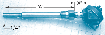
TYPE 21D
Features: 1/4" diameter 316 SS sheath; operating range –320°F to 900°F with universal hardware for spring-loading; single or dual elements;
RdF Reference or IEC/DIN R vs T characteristics, and 2, 3 or 4 wire element configurations. Styles A & B Head Shown.
| 21D | 1/4" Diameter Sheathed Platinum Probe, Spring-Loaded | ||||||||||||||||
| RTD RESISTANCE SPECIFICATIONS (Ohms @ 0°C) | |||||||||||||||||
| 10 11 T01 20 21 T05 T10 102 112 T012 |
100 ± 0.1 (α = 0.003924 Ω/Ω/°C) RdF Ref. Std. 100 ± 0.1 (α = 0.00385 Ω/Ω/°C) IEC/DIN Std. 100 ± 0.12 (α = 0.00385 Ω/Ω/°C) thin film 200 ± 0.2 (α = 0.003924 Ω/Ω/°C) 200 ± 0.2 (α = 0.00385 Ω/Ω/°C) 500 ± 0.6 (α = 0.00385 Ω/Ω/°C) thin film 1000 ± 1.2 (α = 0.00385 Ω/Ω/°C) thin film 100 ± 0.1 Dual Element (α = 0.003924 Ω/Ω/°C) 100 ± 0.1 Dual Element (α = 0.00385 Ω/Ω/°C) 100 ± 0.12 Dual Element (α = 0.00385 Ω/Ω/°C) thin film |
||||||||||||||||
| SERVICE PARAMETER - Sinusoidal Vibration 20Hz to 2kHz | |||||||||||||||||
| S H |
Standard construction (25 g wire-wound, 80 g thin film) Heavy duty construction (up to 50 g) (single wire element only) |
||||||||||||||||
| PROBE LENGTH IN THERMOWELL | |||||||||||||||||
| Std. Const: 2" min, Heavy Duty: 3" min (see photo) Specify length "A" (bore depth) in inches |
|||||||||||||||||
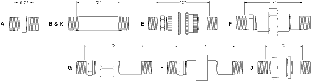
| PROBE LAG HARDWARE - 1/2 NPT Fittings, stainless steel unless noted. | |||||||||||||||||
| A BX EX FX GX HX JX KX |
Hex Nipple is 3/4" long standard. Specify as "A", (standard) (Straight Nipple), specify X=1/8", 1/2", 1" + 1" increments (Aluminum Union/Nipple Extension), specify X=min. 3" plus 1" increments Same as EX (stainless union) (Coupling/nipple extension), black iron, specify X=min. 3" + 1" increments (Union/nipple extension), black iron, specify X=min. 3" + 1" increments (Close nipple, galvanized unsealed parting coupling, nipple extension) black iron, specify x=min. 1 1/2" + 1" increments (shortest “union”) (Straight nipple) black iron, specify x=1/8", 1/2", 1", + 1" incr. (CREDIT) |
||||||||||||||||
| CONNECTION HEAD (see connection head table) | |||||||||||||||||
| NUMBER OF LEADS | |||||||||||||||||
| A B C D E |
Single element, 2 wires any length Single element, 3 wires 36" or under in length Single element, 4 wires 36" or under in length Dual element, 2 wires per element Dual element, 3 wires per element |
||||||||||||||||
| LEAD LENGTH (Specify in inches) (4" Standard) |
|||||||||||||||||
|
– |
|
– |
|
– |
|
– |
|
– |
|
– |
|
– |
|
– | Typical Write-Up for 21D | ||||||||||||||||||||||||||||||||||||||||||||||||||||||||||||||||||||||||||||||||||||||||||||||||||||||||||
 |
|
|
|
|
|
|
|
|
|
|
|
|
|
|
|
|
|
|
|
|
||||||||||||||||||||||||||||||||||||||||||||||||||||||||||||||||||||||||||||||||||||||||||||||||||||||
LAG HARDWARE REFERENCE
PERFORMANCE SPECIFICATIONS
|
Features Operating Temperature Range Resistance(Ohms @ 0 °C) Temperature Coefficients Accuracy Stability |
Time Constant without Thermowell Vibration Self Heating Insulation Resistance Recommended Current Pressure Rating Lead Materials |
||||
|
Teflon® is a registered trademark of the DuPont Corporation. |
|||||
SCHEMATIC DIAGRAM
Visit our Accessories pages for more information on Connection Heads, Thermowells and more:
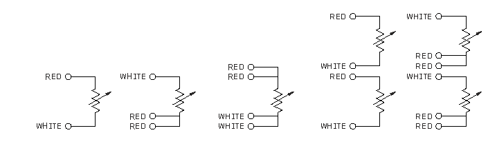
LEAD REFERENCE
