

Heat Flux Sensors
RdF Heat Flux Sensors are used for the precise measurement of heat loss or gain through materials.
To simplify the measurement of thermal transfer or movement, RdF has developed a unique line of Micro-foil® Heat Flux Sensors to meet a broad range of measurement applications. Specifically, these heat flux sensors are designed to obtain a precise, direct reading of thermal transfer through a surface in terms of energy per unit time, per unit area.
Standard and custom RdF Heat Flux Sensors are used in a myriad of R&D and flight applications.
HEAT FLUX VS SURFACE TEMPERATURE MEASUREMENT
Surface temperature measurement techniques are well known and are perfectly satisfactory for applications in which only the immediate, single surface temperature data is required. However, the temperature of a single or outer surface is typically the result of a thermal condition acting upon an inner surface as well as the thermal properties of the total material thickness.
Heat flux sensing devices are the practical way of accurately measuring the thermal activity at one material surface resulting from thermal events at both sides of that material. A change in heat transfer is also a large directional signal preceding significant temperature change, providing a new tool for critical process control.
-
Heat Flux Sensors are used to measure the rate of heat transfer through a surface. This measurement is expressed as Watts per square meter (W/m²) or BTU/hr*ft².
The sensor consists of a differential thermopile. A small temperature difference develops across the sensor as heat flows through and generates a voltage output which is proportional to the heat flow.
RdF’s Micro-foil® Heat Flux Sensors are especially thin and flexible, minimizing the impact of the sensor on the measurement itself. They are particularly well-optimized for application to curved surfaces or laminated between layers of material.
Their sensitivity is controlled by the thickness of the thermal barrier and the number of thermocouple junctions within the sensor.
-
The voltage to heat flow proportion is typically expressed as:
q=k(ΔT/d)
In RdF Micro-foil® Heat Flux Sensors, the heat flow is measured perpendicularly to the flat surface of the sensor. The microvolt output will be positive or negative, providing both the heat flow rate and direction of flow. It is common to see the output switch from positive to negative (and vice versa) as the heat flow changes.
Each RdF Micro-foil® Heat Flux Sensor is individually calibrated and supplied with serialized data.
The sensors are very thin and flexible, and attach to flat or curved surfaces without damaging those surfaces. They require no special wiring, reference junction or signal conditioning.
Connect the sensor to any direct-reading microvolt meter or data system. Upon connecting the leads, the sensor provides a direct measurement of the heating or cooling transfer rate through both the sensor and its mounting surface.
-
Heat flow is averaged across the surface of the sensor. In many applications, we generally suggest minimizing the surface area to enable point measurement vs general area characterization.
For applications where average heat flux over large non-uniform areas is desired, RdF PN 27160 can be produced in arrays.
Please do not hesitate to reach out to us for more information and application support.
HOW RDF’S MICRO-FOIL® HEAT FLUX SENSORS WORK - A Simplified Explanation
The function of a heat flux sensor is to measure heat transfer (loss or gain) through the surface where it is mounted. It does this by indicating temperature difference between opposite sides of a thin layer of separator material to obtain a direct measurement of the heat loss or gain through the separator material. The same measured heat must flow through the sensor cover layers on each side of the separator material and the surface where the sensor assembly is mounted.
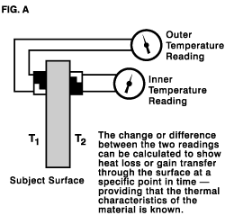
Before heat flux sensors were developed, the typical method for determining heat gain/loss transfer was to install two temperature-measuring devices, one on either side of the subject material. (See Figure A). The difference between the two temperature readings was then used to calculate heat loss or gain per unit area and unit time through the surface provided the thermal characteristics of the subject material were known.
In most situations it is neither desirable nor possible to install temperature-measuring devices on both sides of a rigid material — even if thermal characteristics of the material are known. The heat flux sensor reports these same heat transfer measurements from a single, convenient surface with instantaneous readout. In addition, precise properties of the surface material are not required.
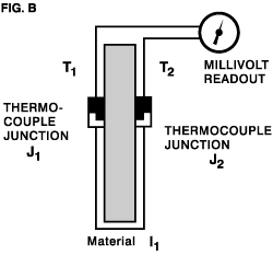
In our simplified explanation, heat flux sensor (see Figure B) construction is much like the example shown in Figure A. Two temperature–measuring thermocouple elements are physically separated by a thermal insulating material, but now oriented and connected to oppose each other. Combined output is zero when there is no temperature difference. When the heat begins to “transfer” through surface and increase (T₁), junction (J₁) generates an increased voltage. As the heat passes through the material (I₁) to reach thermocouple junction (J₂), the voltage at (J₁) is always higher to generate a differential voltage output. As the temperature of J₁ is warmer (or cooler if heat is coming from the other direction) than the temperature of J₂ , that temperature differential, creates a similar and directional differential in voltage. Since the temperature differential is proportional to heat flow/unit area and unit time, so is the voltage differential output, with its polarity indicating the direction of the heat flow.
If such a heat flux device were to be embedded within a subject material, it would tend to become an integral part of that material—duplicating and reading out the heat transfer/unit area and unit time through the composite material and sensor.
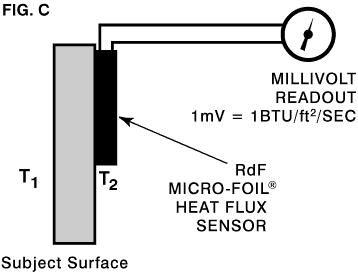
Due to the unique design of the RdF Micro-Foil® Heat Flux Sensors it is not necessary to implant or in any way damage or invade the subject surface in order to achieve highly reliable and precise readings. (See Figure C). The RdF Heat Flux Sensors are extremely thin and flexible so that when properly mounted they become virtually a “component” of the subject surface. The RdF Heat Flux Sensor faithfully simulates the action and reaction of the temperature changes (transfer of heat) at the sensor mounting surface because the same heat must flow though one, then the other.
UNIQUE CONSTRUCTION
Conventional heat flux sensors fabricated with wire tend to create excessive thermal losses at the edges of the sensor because they are at least 10 times thicker than RdF sensors. Most are also rigid, applicable only on flat surfaces.
RdF’s patented Micro-Foil® Heat Flux Sensors are fabricated with special homogeneous alloys and extremely thin foil legs between junctions. This enables thin and flexible construction. Equally important, RdF forms the sensor junctions in high heat flux sensors by a unique process that joins dissimilar metal foils without any overlap so ideal heat flow is not diverted. The complete fabrication process produces in a very thin, strong, and flexible sensor unit.
CALIBRATION
RdF Micro-Foil® Heat Flux Sensors are individually calibrated at a base temperature of 70°F (21°C). Generally, the sensor is calibrated for low levels by conduction in heat flow series with a traceable standard. The result is a calibration constant for microvolt output per unit of heat transfer rate. Models with heat sinks for high heat flux are calibrated for millivolt output at traceable levels of thermal radiation over the range and a curve is supplied. Calibration curves are typically linear. Each sensor is individually packaged with its calibration data.
Check out our Application Note for a deeper dive into the use of these sensors, including more detail on RdF’s calibration.
Selected Heat Flux Sensors are available now in our webstore:

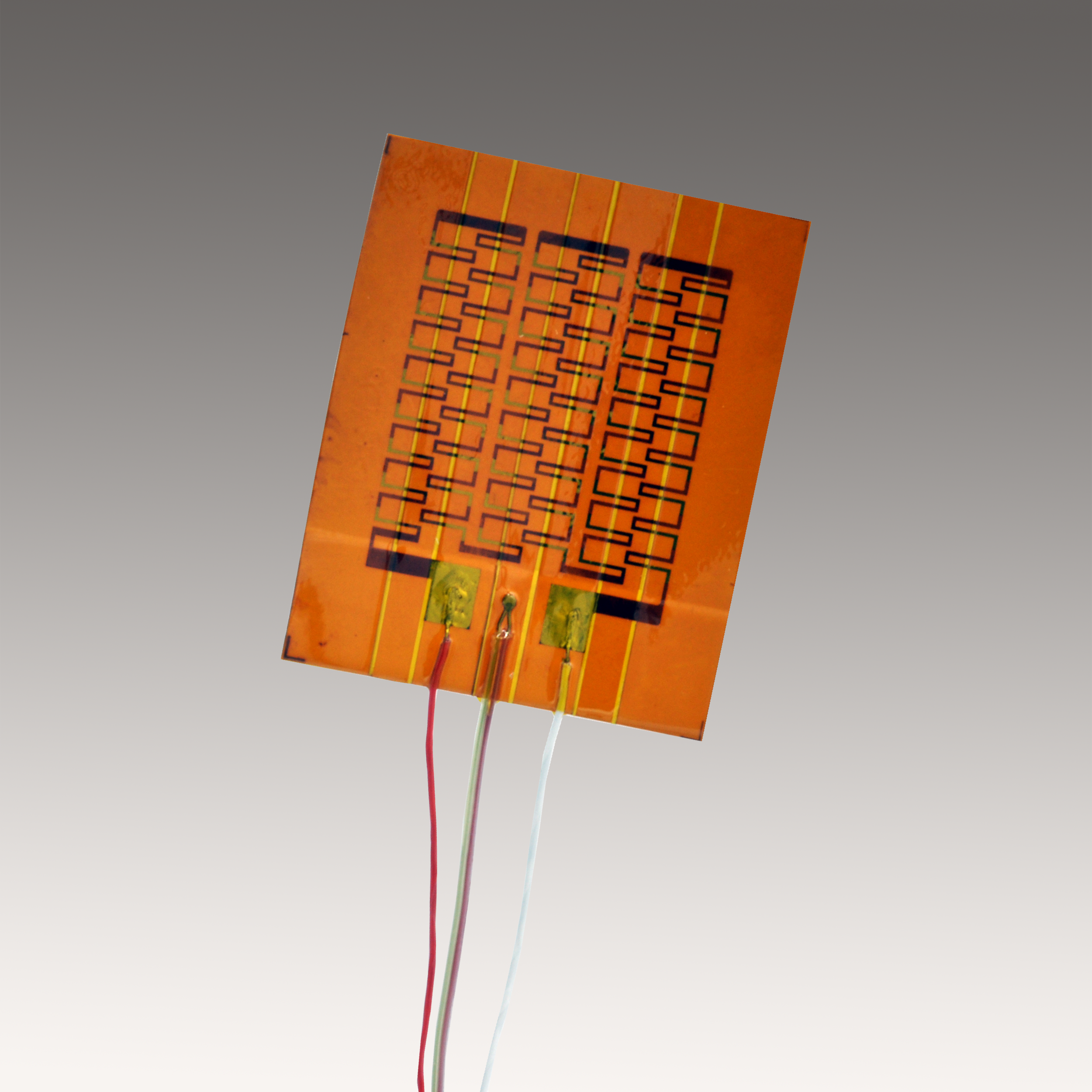
Paper-thin, flexible RdF Micro-Foil™ Heat Flux Sensors easily attach to any flat or curved surface and are completely non-invasive.
For precise measurement of heat transfer (loss or gain) through any material surface.